


Today’s Web Exclusive comes from Don Clark, president of Efficiency Technologies, Inc. of Tulsa, OK. Clark has over 25 years in the fluid dynamics, water treatment and chiller industries. He can be reached at (866) 333-8321.
To understand refrigerant “stacking” and “carryover,” you must first be familiar with the cooling cycle for water-cooled chillers. To begin, chillers circulate “chilled water” in a closed loop system from the evaporator to air-handlers where heat is transferred from the circulating air to the “chilled water” (Figure 1A). The warmed water returns to the evaporator where heat is transferred from the water to a cold, low-pressure liquid refrigerant (Figure 1B). The compressor creates a continuous low-pressure in the evaporator, making it possible for the liquid refrigerant to boil into a low-pressure vapor (Figure 1C). This vapor absorbs the heat and transfers it out of the evaporator into the compressor (Figure 1D). Once inside the compressor, the low-pressure vapor is compressed into a hot, high-pressure vapor (Figure 1E). The high-pressure vapor discharges from the compressor and enters the condenser where the heat is transferred to the colder condenser water circulating from the cooling tower basin (Figure 1F). Removing the heat from the high-pressure vapor causes it to condense into a warm, high-pressure liquid. Additional heat can be removed from the high-pressure liquid refrigerant through a sub-cooler or storage vessel in the condenser prior to returning to the evaporator … where the process begins again. The heat transfer is completed when the condenser water leaves the chiller and circulates to the open cooling tower, where heat is removed by evaporation to the atmosphere, causing the water temperature to drop prior to returning back to the condenser (Figure 1G).
Figure 1. The Cooling Cycle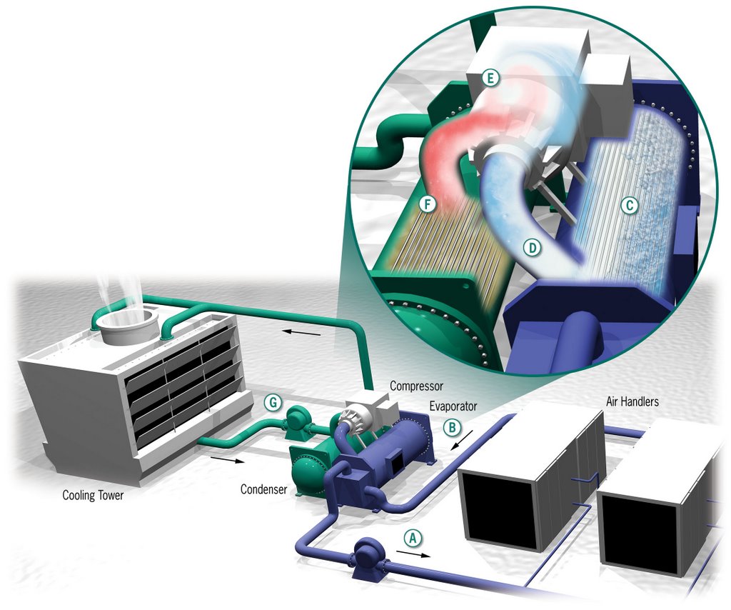
Stacking is the abnormal accumulation of refrigerant in the condenser, commonly caused by a decrease in the difference in pressure or “lift” between the condenser and the evaporator. This reduced pressure drop prevents the refrigerant’s ability to physically flow back to the evaporator and maintain a normal refrigerant cycle.
Carryover is the presence of liquid refrigerant droplets in the cold, low-pressure vapor produced in the evaporator. Generally, there are two types of carryover. The first type is by design and controlled with the intent of enhancing the lubrication process in the compressor. The second type is not by design, and if excessive can be detrimental to the performance and reliability of a chiller. When this occurs, liquid refrigerant droplets travel from the evaporator to the compressor inlet (Figure 2).
Figure 2. Refrigerant Carryover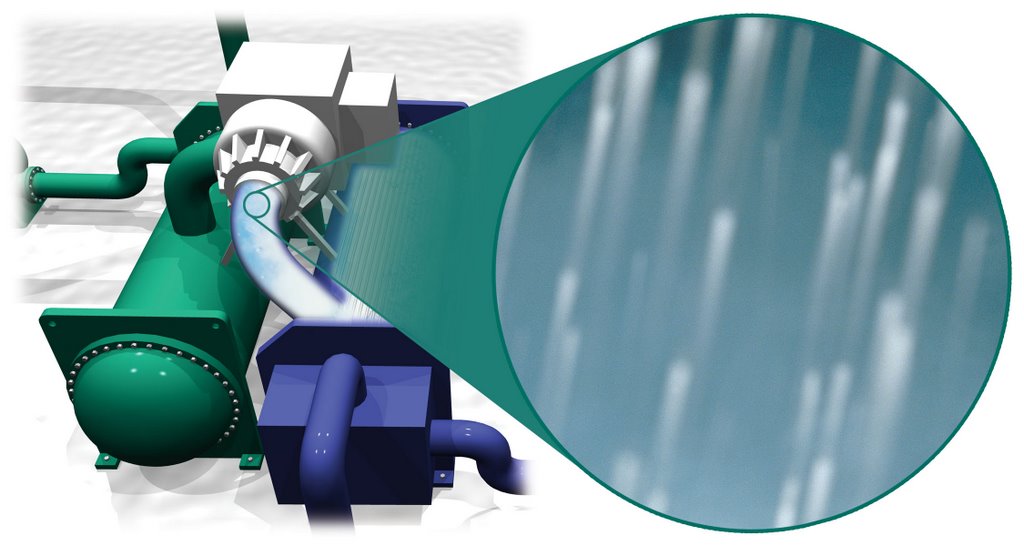
As these liquid droplets enter the compressor system they vaporize on the metal internals, stripping away lubricant. Ultimately this oil stripped from the compressor becomes entrained in the hot, high-pressure refrigerant vapor and enters the condenser. Once this happens, oil from the sump is used to replace the stripped oil, causing the oil level to drop in the compressor oil reserve (see Compressor Oil Levels Drop section). Entrained oil travels with the refrigerant as it condenses from the hot, high-pressure vapor to the warm, high-pressure liquid in the condenser. The excessive oil in the warm liquid refrigerant then returns to the evaporator where the oil separates from the refrigerant. Once separated, the oil can be removed and return to the compressor oil reserve. Also, in severe cases, carryover can cause excessive liquid refrigerant to accumulate (stack) in the condenser.
Although stacking and carryover occur under similar conditions in a chiller, they can develop together or separately. Identifying and preventing these conditions are covered throughout this article.
Stacking and carryover can be very common, affecting all types of water-cooled chillers. However, low-pressure chillers, which operate the evaporator in a vacuum, are more susceptible. Compared to high-pressure chillers, they do not have a large difference in refrigerant pressure between the condenser and evaporator. Figure 3 illustrates the comparison of a low-pressure chiller using R-123 refrigerant and a high-pressure chiller using R-134 refrigerant. At 65°F Entering Condenser Water Temperature (ECWT) and 40°F evaporator chill water temperature, the pressure difference in the R-123 machine is 4.5 psi. The pressure difference in the R-134 machine is 28.9 psi. It is this “lift” in both chillers that can be beneficial or detrimental if not properly maintained. To be fair, the advantage of low-pressure chillers is the ability, in most cases, to achieve a lower Full Load Design (FLD) kW/Ton. Depending on plant design and operations, both types have their advantages.
Figure 3. Pressure/Temperature Chart Comparison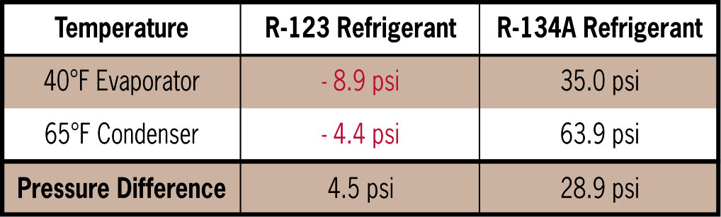
There are three conditions that cause stacking and carryover: mechanical, maintenance and the most common … operational.
Mechanical Problems. There are three tower temperature control problems that can cause stacking and carryover in chillers. First is the location of the tower temperature control. This temperature should mirror the ECWT. Second, historesis is the delayed reaction time of the controller affecting the ability to maintain a tight temperature range. The third and most common problem is tower operations maintaining temperatures too cold for the design of the chiller. To remedy these problems, make sure the tower temperature is controlled in the basin, mirroring the ECWT. Improve controls to keep a maximum 2°F high/low temperature range in the tower basin. Maintain the design ECWT for the chiller. All will help contribute to a well-run, efficient plant.
A malfunctioning or un-calibrated refrigerant level control in the condenser can create stacking by not allowing refrigerant to flow back to the evaporator. Refrigerant builds up in the condenser, while at the same time lowering refrigerant levels in the evaporator due to an unbalanced refrigerant cycle. The chiller loses heat transfer efficiency and may shut down on low evaporator refrigerant temperature.
Maintenance Problems. It can be difficult to add the proper amount of refrigerant to a chiller; therefore refrigerant overcharge may occur when the chiller is serviced. This additional refrigerant is added to compensate for the loss during normal operations or leaks (which have been repaired). As a result, stacking and carryover may occur. When this happens, it is generally easy to identify. The obvious signs are higher than normal refrigerant pressures in both the evaporator and condenser after the chiller was serviced. Extreme overcharge will cause the chiller to run poorly or have difficulty staying online due to high condenser head pressure. A superheat te
st is an excellent tool for verifying and ensuring proper refrigerant levels (see Sidebar below).
Operational Problems. The primary cause of stacking and carryover, as it relates to operations, is the operator running the ECWT too low for the chiller load conditions. This can bring about stacking, or in extreme cases, carryover with stacking. Both cause chiller inefficiency and damage over time.
ECWTs can have a good or bad impact on chillers. Lowering the ECWT can be a great energy management practice if done within the chiller design parameters. For example, every 1°F drop in ECWT below FLD can improve a chiller’s efficiency up to 1.5% depending on the chiller design. Lowering the ECWT reduces the “lift”, making it possible for the compressor to use less energy to produce the desired capacity (tonnage). This is extremely valuable, considering the cost of energy today and that chillers are typically the largest energy consumer in most facilities. However, there is a fine line between good energy management and initiating potential problems due to low ECWTs.
Chiller manufacturers today not only build chillers with more efficient FLD kW/Ton, but they can also design chillers to maximize efficiency at part loads. Since most chillers run in part loads ~98% of the time, it is up to the facility to decide which chiller best fits their needs and to master the operation of these chillers to achieve the lowest kW/Ton under all conditions. They must also operate in a manner that protects this very expensive equipment.
In terms of potential savings, a well-run chiller should achieve an overall operating kW/Ton below FLD kW/Ton by 5% to 15% for constant speed drives, and by 20% to 30% for variable speed drives. How can plants achieve this efficiency? Primarily, maintaining the design ECWT for the chiller load and using the operator’s knowledge of the chiller to maximize its performance. There is no substitute for well-trained operating engineers; however, they need the required data and analysis to make informed decisions when operating a chiller to achieve its best efficiency.
Both stacking and carryover affect chiller performance and are not easily detected from a single sensor. In fact, it requires multiple sensors, experienced operators and data analysis to positively identify. Therefore, it is typically only diagnosed in severe cases, usually when the chiller shuts down or after an oil or refrigerant analysis is performed. Furthermore, misunderstanding of these conditions may lead to false assumptions like low oil and refrigerant levels, resulting in excess oil being added to the chiller or refrigerant overcharge.
Compressor Oil Levels Drop. When oil levels drop in the compressor sump due to low ECWT, it can prompt the operator to add additional oil. Later, when the ECWT returns to normal, excess oil separates in the evaporator, where it is removed and returns to fill the compressor oil sump with surplus oil. This surplus oil may need to be manually removed. However, if the chiller continues to run with low ECWTs, low oil levels may persist and even more oil added. This makes it possible for this excess oil to emulsify in the refrigerant and inhibit heat transfer on the evaporator tubes.
Keep detailed records of oil additions between oil changes. When the additions are made, check for leaks. If no leaks exist, examine operations. Look for foaming in the evaporator refrigerant sight gauge as a sign of high oil levels in the refrigerant. Look for refrigerant boiling in the compressor oil sight gauge as a sign of stacking and/or carryover.
Evaporator Liquid Refrigerant Levels Drop. This can happen very quickly or slowly depending on the disparity between the ECWT and chiller load. When severe, the refrigerant is rapidly pulled out of the evaporator and stacked in the condenser. This may cause the chiller to shut down on low refrigerant temperature. The refrigerant cycle is broken due to low lift. Increasing ECWT restores the lift and the refrigerant will go back to a balanced cycle between the condenser and evaporator.
Seasonal cold weather conditions can make tower water basin temperatures difficult to control and the potential for stacking and carryover greater. During startup, lowering the demand limit on the chiller and/or reducing condenser flow may be the easiest solution for providing the desired condenser water temperature.
Oil and Refrigerant Analysis. It is best practice to perform quarterly oil analysis and refrigerant analysis when problems are suspected. Abnormally high metal content in the oil analysis can be an indicator of past refrigerant carryover and bearing wear caused by increased friction from stripping the lubrication. The chiller representative and a physical inspection of the compressor bearings can confirm this. There is an acceptable level of oil that can be in a refrigerant analysis and not impede chiller heat transfer. When refrigerant carryover is chronic, the percentage of oil in the refrigerant will increase, causing heat transfer problems.
Chiller Diagnostics Software. Investing in a chiller diagnostics program, such as EffTrack™, can make it easy to identify stacking and carryover. EffTrack collects, stores, and analyzes chiller operating data to determine performance, diagnose causes of inefficiency, and recommend corrective action. The EffTrack monitoring service notifies plant contacts if problems occur. Plant operators and facility managers can review the hourly updated information by logging in to EffTrack from any computer with Internet access. By following the EffTrack recommendations for improvement, plant operators can eliminate chiller faults and significantly lower the chiller kW/Ton and plant kWh consumption. These savings are identified and measured in the EffTrack Daily Reports (Figure 4). In addition to stacking and carryover, EffTrack can identify high or low refrigerant levels, compressor problems, water flow rate problems including plugged or restricted water flow, fouling and scaling, non-condensable gasses in low-pressure chillers, cycles of concentration problems, and sensor calibration problems or bad data.
Figure 4. EffTrack Daily Report and Refrigerant Stacking Diagnostic
Every chiller has its own unique circumstances that create stacking and carryover. Ask your chiller manufacturer what is the best operating conditions for ECWT and the matching part load values. Then develop a program for monitoring efficiency and identifying chiller problems. Once achieved, the facility can reap the rewards of peak efficiency and performance at the lowest possible expense.
SIDEBAR: SUPERHEAT TEST
The purpose of the superheat test is to identify high or low refrigerant levels. To perform this test, the chiller must be brought up to FLD conditions, i.e., 100% load and typically 85°F ECWT with design water flows.
Superheat Test for Direct Expansion (DX) and Screw Compressor Chillers
Once the chiller is brought up to FLD conditions, measure the temperature on the suction line, close to the compressor. Next, measure the pressure on the suction line. Using a universal pressure/temperature chart*, determine the saturated refrigerant temperature from measured pressure. Subtract the measured temperature from the saturated refrigerant temperature to get the superheat value. Typically, the standard superheat value is between 12°F and 17°F.
Superheat Test for Centrifugal Chillers
Once the chiller is brought up to FLD conditions, measure the temperature on the discharge (high-pressure) line, close to the compressor. Next
, measure the condenser refrigerant pressure. Using a universal pressure/temperature chart*, determine the saturated refrigerant temperature from measured pressure. Subtract the saturated refrigerant temperature from the measured temperature to get the superheat value. Typically, the standard superheat value is between 10°F and 20°F.
A “high” superheat value is an indication of “low” refrigerant levels.
A “low” superheat value is an indication of “high” refrigerant levels.
* A universal pressure/temperature chart can be downloaded at www.EffTec.com/download.html

